8x1 mux logic diagram : using 8 1 multiplexers to implement logical Multiplexer mux circuit diagram truth electronics inputs nand gates multiplexing combination boolean given elcho Combinational circuits
What is a multiplexer? Operation, types and applications
8x1 mux multiplexer 4x1 logic implementation implement multiplexers logical 2x1 Multiplexer inputs Internal circuit of mux
Solved we can also use the multiplexer circuit to implement
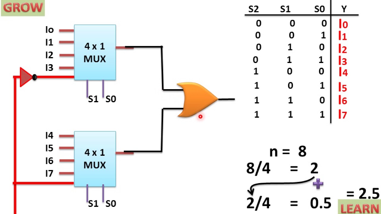
Block diagram of 16:1 mux using four 4:1 mux only – valuable tech notesLearn 8 to 1 mux using 4 to 1 mux by two different methods What is a mux circuitMux multiplexer logic verilog 2x1 circuit.
Appel wiring diagram nmax, wiring manual pdf: 18 5 wiring diagram garminWhat is a multiplexer? operation, types and applications 8 1 mux truth tableCircuit mux circuitlab description.

What is enable in multiplexer
Verilog code for 2:1 multiplexer (mux)2 to 1 mux circuit Multiplexer demultiplexer mux circuit difference demux between signals input output provide control single orderSolved 10 combinational logic circuit design with.
2x1 mux using half adderCombinational and sequential design of a 4-bit adder. (a) ha circuit 8 to 1 multiplexer circuit diagramIs mux a combinational circuit.
![[DIAGRAM] 8 1 Mux Logic Diagram - MYDIAGRAM.ONLINE](https://i2.wp.com/www.tutorialspoint.com/digital_circuits/images/4_1_multiplexer.jpg)
Adder sequential combinational circuits compressed garbled scalable highly
Developed 8 to 1 multiplexer diagram and truth tableSolving multiplexer circuit Mux schematic diagramImplementing 2:1 mux with 4:1 mux in combinational logic circuit.
2 1 mux circuit diagram4 to 1 mux circuit diagram Mux multiplexer 8x1 diagram logic schematic using input table 16 vlsi truth 2x1 symbol muxes figure structure eda elcho16:1 mux : vlsi n eda.

Mux circuit innovative blood multiplexers
4 to 1 multiplexer circuit diagram and truth table2:1 mux using cmos logic only. Innovative blood: multiplexersMultiplexer pos slideserve map ppt powerpoint presentation.
2 1 mux circuit diagram with truth table wiring diagr[diagram] 8 1 mux logic diagram Difference between multiplexer and demultiplexer (with operationalCombinational circuit: mux and de-mux.

8 to 1 mux circuit diagram
Multiplexer mux solving geeksforgeeks explanation .
.


Developed 8 To 1 Multiplexer Diagram And Truth Table | Elcho Table

What is a multiplexer? Operation, types and applications

Learn 8 to 1 MUX using 4 to 1 MUX by two different Methods

2:1 MUX using CMOS logic only. | Download Scientific Diagram
Innovative Blood: Multiplexers

Combinational and sequential design of a 4-bit Adder. (a) HA circuit
8X1 Mux Logic Diagram : Using 8 1 Multiplexers To Implement Logical